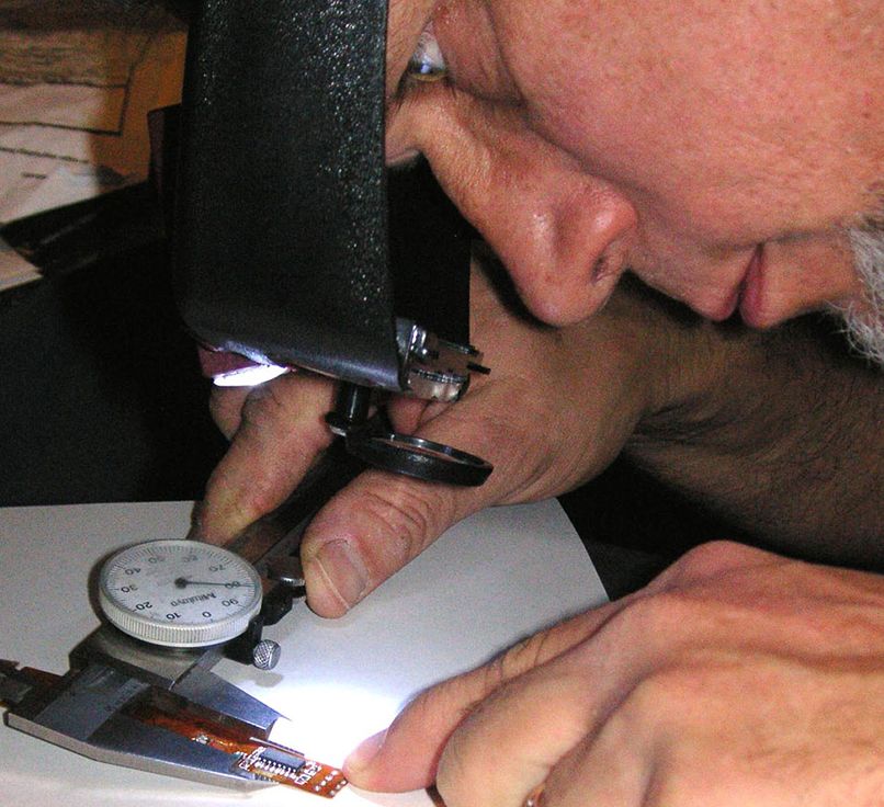
Every now and then a call comes into the CAD cave that goes something like this: “I’ve got a broken flex circuit and I need to buy a replacement, but I don’t have any drawings and I have no idea who made it.” Time for reverse engineering!
I love working on these projects – each is a mystery to be solved. As Hercule Poirot would say they exercise “the little grey cells”. In this article, I’ll share the eight steps I use for reverse engineering a flex circuit.
I use AutoCAD, Electronics Packaging Designer (EPD), Photoshop, a flatbed scanner, an ohm meter, a good magnifier, and two calipers – a digital one that measures in both inches and millimeters, the other a dial caliper that measures in inches.

Flex circuits are unique—they are neither purely mechanical nor purely electrical. Many PCB designers are available, but very few know the intricacies of flex circuits!