logo - flexible printed circuits - Flex Circuits
Categories
Uncategorized

Ninja Flex Circuits – Black Cover and Shielding Films

Ninja Flex Circuits – Black Cover and Shielding Films

One thing that I’ve always liked about flex circuits is that they look cool! Shiny, orange, and clear you can see those beautifully curved copper traces, unlike their green rigid-board counterparts.

But if you’ve looked inside a smartphone or seen a teardown article on an iPhone you don’t see beautiful shiny flex circuits – you see flex circuits that look like they were spray-painted with black primer.

Do not be deceived by their drab appearance – these are Ninja flex circuits! They have special coverfilms that give them powers to suppress EMI, eliminate glare, control impedance, and reduce cost. They also, disguise and protect intellectual property – it takes a great deal of effort to reverse engineer them and you literally destroy the circuit in the process.

Ninja | Flexible PCB –rigid flex design guide
Categories
Uncategorized

Pictures So Good You Can See Flex Circuits!

Pictures So Good You Can See Flex Circuits!

Big kudos to the folks at Jet Propulsion Laboratory for the continued success of their Mars rover programs. Curiosity has been performing flawlessly since landing in Gale Crater back in August.

As mentioned in an earlier PCB007 article (June 2008) I had a very small part in creating the flex circuits for Curiosity – creating trace layouts for about a dozen flex circuits and checking gerber files for most of the flex circuits in the rover. It was great fun to be part of such an ambitious program, but I never got to actually see the flex circuits themselves. What a pleasant surprise to find the pictures that Curiosity is sending back are so good you can see the flex circuits!

In October the mission used the Mars Hand Lens Imager (MAHLI), which is the camera out on the very end of the robot arm, to capture a set of 55 high-resolution images, which were stitched together to create a high-resolution full-color self-portrait.

flexible printed circuits | rigid flex
Categories
Uncategorized

How To Reverse Engineer Flex Circuits

How to Reverse Engineer Flex Circuits

Every now and then a call comes into the CAD cave that goes something like this: “I’ve got a broken flex circuit and I need to buy a replacement, but I don’t have any drawings and I have no idea who made it.” Time for reverse engineering!

I love working on these projects – each is a mystery to be solved. As Hercule Poirot would say they exercise “the little grey cells”. In this article, I’ll share the eight steps I use for reverse engineering a flex circuit.

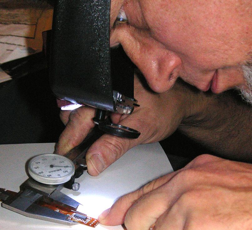
I use AutoCAD, Electronics Packaging Designer (EPD), Photoshop, a flatbed scanner, an ohm meter, a good magnifier, and two calipers – a digital one that measures in both inches and millimeters, the other a dial caliper that measures in inches.

rigid flex design guide | flexible circuits